
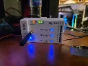
Hardware specifications
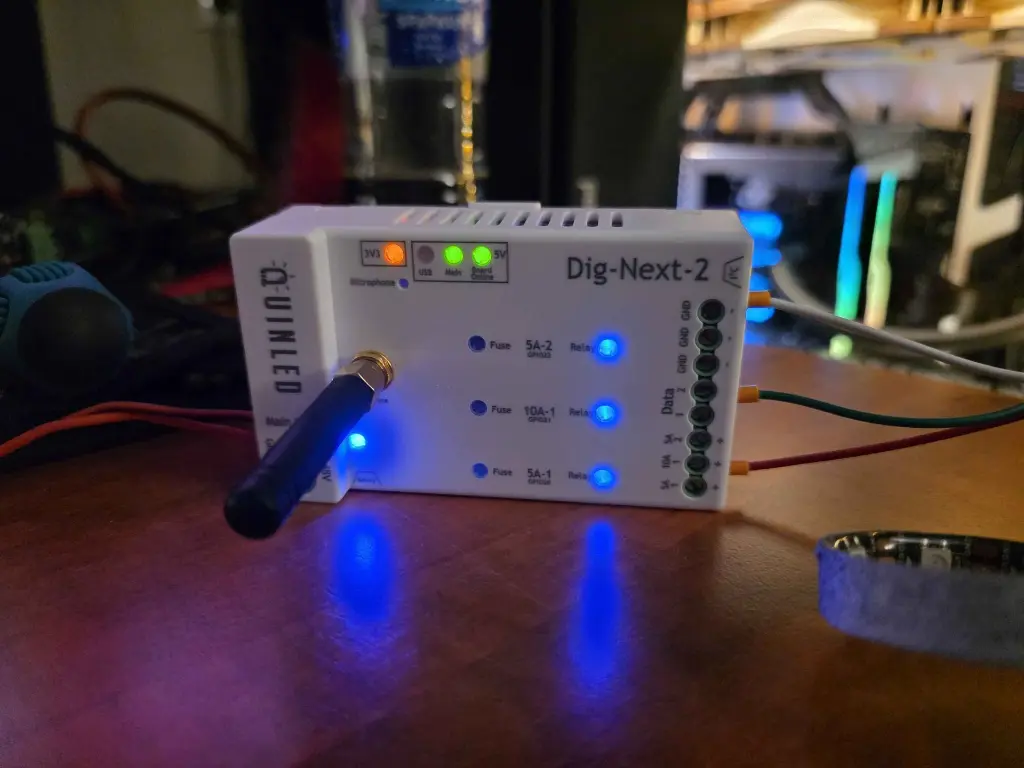
- ESP32 based
- Dual-Core 240Mhz microcontroller
- 8MB Flash
- 2MB PSRAM
- WiFi connected
- 2.4Ghz WiFi built-in
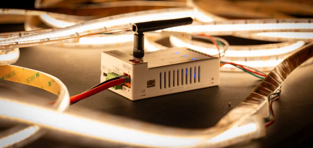
- External Antenna for best WiFi reception possible
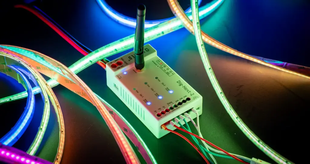
- 2x Green 5.08mm Data output output terminals
- 2x Individual level-shifters
- Re-imagined output stages, no more resistor switcher but long cables with seperate or bundled cables!
- ESD and OverVoltage protected
- A continuous direct short to the data terminal with up to 48V will not kill the hardware
- ESD events (lightning storm, etc.) are also protected!
- 1x Orange 6.35mm Power input terminal
- 3x Red & Black 5.08mm Power output terminals
- Accept up to 14AWG with a wire ferrule
- Individual per channel “relay” On/Off control
- Turned off on the + side so when off nothing can short!
- Individually fused per output channel
- User replaceable fuses
- 2x 5A channel
- 1x 10A channel
- Various internal circuit fuses
- In the case a component fails there are various internal circuit fuses preventing a catastrophic failure
- Auto and True 5V-48V support
- Full range so compatible with newer 36V and 48V LED offerings!
- True means also allowing voltages below 5V so that when voltage drop occurs to say 4.5V the controller doesn’t crash and still provides a stable 5V data output signal to the LED ICs.
- Designed for high current
- Suggest max power is 15A but the board can easily handle the max 20A current possible with the default fuse set (it is not recommended to increase fused values). The controller has been lab tested up to 30A without any issues.
- Dual Power-In feature
- Allows for 2 power supplies to be connected to keep the board
running in “standby” mode while the large LED power supply is
automatically turned on and off.
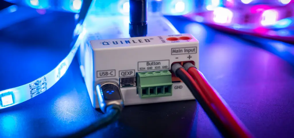
- Large 6.35mm main power input terminals
- Accepts up to 12AWG/4mm2 with wire ferrule
- USB-C as a second power input
- Accepts USB-C 5V
- Large 6.35mm main power input terminals
- Allows for 2 power supplies to be connected to keep the board
running in “standby” mode while the large LED power supply is
automatically turned on and off.
- Built in Microphone
- Various expansion options
- Button Terminals
- 4p 3.08mm pluggable terminal with 2x HW debounced button input (pulled-high) and 2x GND terminal
- External relay port
- JST PH
- Pluggable cable delivered with controller
- Provides (always) 5V, 5V trigger (max 500mA) and GND
- JST PH
- I2C port
- Stemma QT compatible I2C port
- 3V3, GND, 2x GPIO
- QEXP port
- 3V3, GND, 4x GPIO
- Connect various accessories, sensors, etc.
- 3V3, GND, 4x GPIO
- Button Terminals
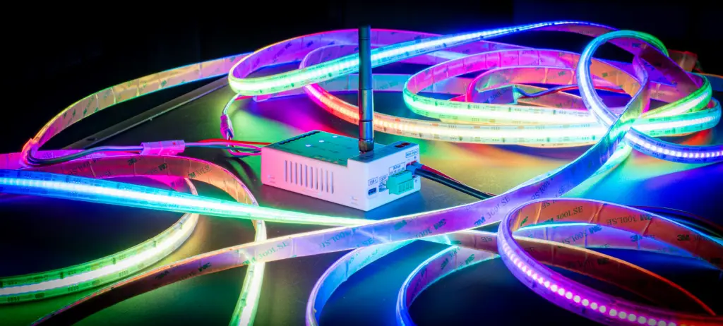
- 100% compatible with WLED, ESPhome, FastLED, Moonlight, etc. etc.
- It’s your hardware, you can run whatever software you like and is best suited for your installation!
- Fully stress and error tested
- Designed to be safe!
- CE certified
Suggested LED handling capabilities
Although the ESP32 can handle a good amount of LEDs it’s capabilities are limited. The suggested max amount of LEDs per board are also dependent on the software you are running on the board.
- WLED
- For WLED a total of ~1200 LEDs divided over the 2 output ports (600 per port) is suggested to keep a decent framerate
- ESPixelstick v4 the same amount as WLED is suggested
- FastLED the same amount as WLED is suggested
- Moonlight the same amount as WLED is suggested
Product contents:
- QuinLED Dig Quad LED controller board
- QuinLED ESP32 WIFI module with USB-C interface *Depends on Variant
- 5x 5A ATO fuses
- NEW - bigger screw terminals for easier cable management
- Pre flashed WLED firmware for instant use
What's in the Box?
Normal version
For the Normal Dig-Next-2 you’ll receive the following in this box:
-
The Dig-Next-2
- Fully assembled in plastic case
- 2x 5A and 1x 10A fuse pre-installed
-
WiFi Antenna
- Easily screws on to top
-
Relay Cable (3pin PH to wire)
- Red = (always) 5V
- Black = GND
- Yellow = (always) 5V trigger
- Easy to connect an external relay board for auto turn on/off main power supply feature
-
QEXT Cable (2×3 pin PHD to female dupont)
- Red = (always) 3V3
- Black = GND
- Yellow = GPIO_0
- Green = GPIO25
- Blue = GPIO32
- White = GPIO33
- Can be used to connect various external boards or extra buttons, etc.
- Info card/Manual
DIN version
If you opt to buy the DIN version you get the following extra:
- Custom mounting plate
- With holes for screw mounting or using a hook and loop strap
- DIN Rail adapter clip
- Screws to screw DIN rail adapter clip into mounting plate
Videos:
- QuinLED-Dig-Next-2 Specification page
- Wiring Guide
- WLED setup tutorial (also phone app)
- QuinLED WLED Home Assistant integration
- Showcase for various LED effects
- Introduction on different types of LED strip, string and panels
Flash the latest firmware online here:
More details and resources here:
Some accessories you made need for your install
Some links are affiliate links and we may earn a small commission when you purchase through the link, your price does not change and it doesn't affect any deals or coupons either.
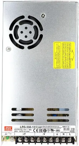
Power Supply:
We always suggest Meanwell power supplies, very reliable and actually give you the power they state.

Fuses:
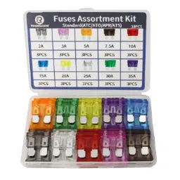
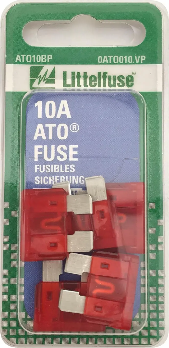
You will need ATO encase you miss-wire or blow the included unit, it's always better to have some spares. There is a lot of cheap versions on fuses on amazon, I've used the below fuses without much issue but if you want a quality fuse stick with Littlefuse or Bussman Fuses

Misc. Accessories:
We sell a variety of accessories to help with your install like out Self-Closing Spit Braided Loom and our Dual Wall Adhesive Lined Heat Shrink to help make water tight connections